The Text3D node is a 3D version of the 2D Text+ node. The controls for this node are mostly identical to the controls for the 2D version in almost all respects, except Text 3D supports only one shading element.
The Text 3D node was based on a tool that predates the Fusion 3D environment. So, some of the controls found in the basic primitive shapes and geometry loaders, such as many of the material, lighting, and matte options, are not found in this node’s controls. The Text 3D node has a built-in material, but unlike the other 3D nodes it does not have a material input. The Shading tab contains controls to adjust the diffuse and specular components. To replace this default material with a more advanced material, follow the Text Plus node with a Replace Material 3D node. The Override 3D node can be used to control the lighting, visibility, and matte options for this node.
When network rendering a comp that contains Text 3D nodes, each render machine is required to have the necessary fonts installed or the network rendering fails. Fusion does not share or copy fonts to render slaves.
Text 3D Node Inputs
SceneInput
The orange scene input accepts a 3D scene that can be combined with the 3D text created in the node.
ColorImage
The green color image input accepts a 2D image and wraps it around the text as a texture. This input is visible only when Image is selected in the Material Type menu located in the Shading tab.
BevelTexture
The magenta bevel texture input accepts a 2D image and wraps it around the bevel as a texture. This input is visible only when one Material is disabled in the Shader tab and Image is selected in the Bevel Type menu.
Text 3D Node Setup
The Text 3D node generates text, so most often this node starts a branch of your node tree. However, to apply more realistic materials, a replace Material node is often added after the Text 3D, prior to connecting into a Merge 3D node.
Text 3D Node Text Tab
The Text 3D text tab in the Inspector is divided into three sections: Text, Extrusion, and Advanced Controls. The Text section includes parameters that are familiar to anyone who has used a word processor. It includes commonly used text formatting options. The Extrusion section includes controls to extrude the text and create beveled edges for the text. The Advanced controls are used for kerning options.
Text section
Styled Text
The Edit box in this tab is where the text to be created is entered. Any common character can be typed into this box. The common OS clipboard shortcuts (Command-C or Ctrl-C to copy, Command-X or Ctrl-X to cut, Command-V or Ctrl-V to paste) also work; however, right-clicking on the Edit box displays a custom contextual menu with several modifiers you can add for more animation and formatting options.
Font
Two Font menus are used to select the font family and typeface such as Regular, Bold, and Italic.
Color
This control sets the basic tint color of the text. This is the same Color control displayed in the Material type section of the Shader tab
Size
This control is used to increase or decrease the size of the text. This is not like selecting a point size in a word processor. The size is relative to the width of the image.
Tracking
The Tracking parameter adjusts the uniform spacing between each character of text.
Line Spacing
Line Spacing adjusts the distance between each line of text. This is sometimes called leading in wordprocessing applications.
V Anchor
The Vertical Anchor controls consist of three buttons and a slider. The three buttons are used to align the text vertically to the top, middle, or bottom baseline of the text. The slider can be used to customize the alignment. Setting the Vertical Anchor affects how the text is rotated but also the location for line spacing adjustments. This control is most often used when the Layout type is set to Frame in the Layout tab.
V Justify
The Vertical Justify slider allows you to customize the vertical alignment of the text from the V Anchor setting to full justification so it is aligned evenly along the top and bottom edges. This control is most often used when the Layout type is set to Frame in the Layout tab.
H Anchor
The Horizontal Anchor controls consist of three buttons and a slider. The three buttons justify the text alignment to the left edge, middle, or right edge of the text. The slider can be used to customize the justification. Setting the Horizontal Anchor affects how the text is rotated but also the location for tracking (leading) spacing adjustments. This control is most often used when the Layout type is set to Frame in the Layout tab.
H Justify
The Horizontal Justify slider allows you to customize the justification of the text from the H Anchor setting to full justification so it is aligned evenly along the left and right edges. This control is most often used when the Layout type is set to Frame in the Layout tab.
Direction
This menu provides options for determining the direction in which the text is to be written.
Line Direction
These menu options are used to determine the text flow from top to bottom, bottom to top, left to right, or right to left.
Write On
This range control is used to quickly apply simple Write On and Write Off animation to the text. To create a Write On effect, animate the End portion of the control from 1 to 0 over the length of time required. To create a Write Off effect, animate the Start portion of the range control from 0 to 1.
Extrusion section
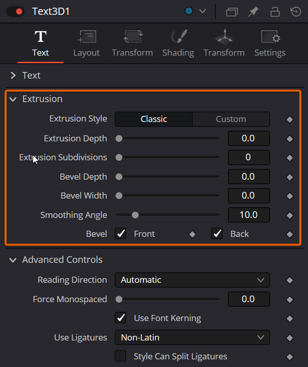
Extrusion Depth
An extrusion of 0 produces completely 2D text. Any value greater than 0 extrudes the text to generate text with depth.
Bevel Depth
Increase the value of the Bevel Depth slider to bevel the text. The text must have extrusion before this control has any effect.
Bevel Width
Use the Bevel Width control to increase the width of the bevel.
Smoothing Angle
Use this control to adjust the smoothing angle applied to the edges of the bevel.
Front/Back Bevel
Use these checkboxes to enable beveling for the front and back faces of the text separately.
Custom Extrusion
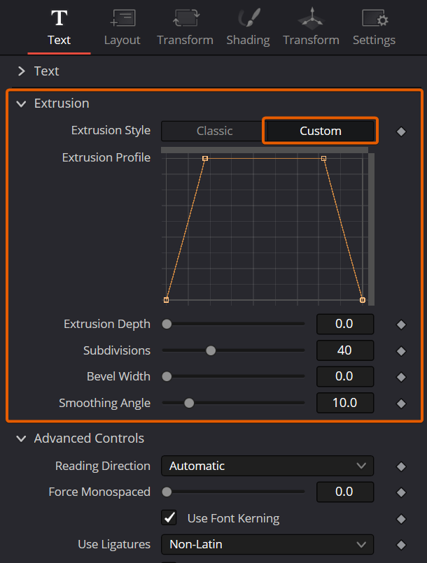
In Custom mode, the Smoothing Angle controls the smoothing of normals around the edges of a text character. The spline itself controls the smoothing along the extrusion profile. If a spline segment is smoothed, for example by using the shortcut Shift-S, the normals are smoothed as well. If the control point is linear, the shading edge is sharp. The first and last control points on the spline define the extent of the text.
Custom Extrusion Subdivisions
Controls the number of subdivisions within the smoothed portions of the extrusion profile.
Advanced Controls
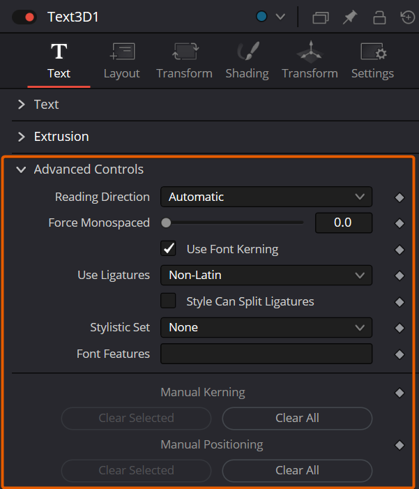
Force Monospaced
This slider control can be used to override the kerning (spacing between characters) that is defined in the font. Setting this slider to zero (the default value) causes Fusion to rely entirely on the kerning defined with each character. A value of one causes the spacing between characters to be completely even, or monospaced.
Use Font Defined Kerning
This enables kerning as specified in the True Type font and is on by default.
Manual Font Kerning
Manual Font Kerning is only performed using the Text+ node. To perform manual kerning on Text3D, create the text using the Text+ node and kern it in that tool. Then, right-click over the tool’s name in the Inspector and choose Copy. Once the settings are copied, select the Text 3D node and choose Paste Settings from the Inspector’s contextual menu. Once the manual kerning is pasted in the Text 3D node, the two buttons in the Inspector clear either the selected character’s kerning or all the kerning adjustment in the current text.
Text 3D Node Layout Tab
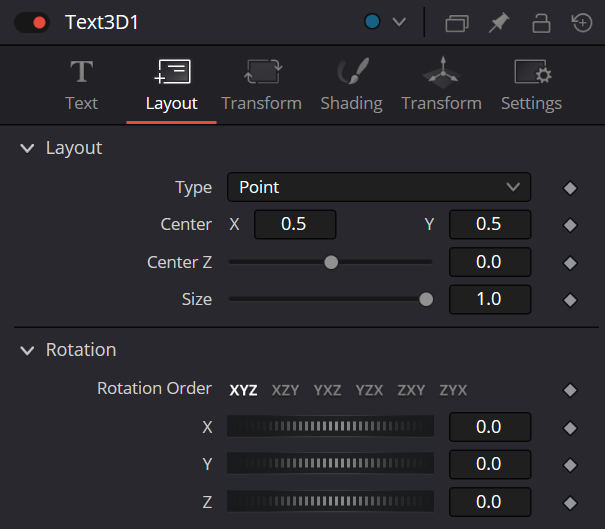
The Layout Tab is used to position the text in one of four different layout types.
Layout Type
This menu selects the layout type for the text.
Point
Point layout is the simplest of the layout modes. Text is arranged around an adjustable center point.
Frame
Frame layout allows you to define a rectangular frame used to align the text. The alignment controls are used to justify the text vertically and horizontally within the boundaries of the frame.
Circle
Circle layout places the text around the curve of a circle or oval. Control is offered over the diameter and width of the circular shape. When the layout is set to this mode, the Alignment controls determine whether the text is positioned along the inside or outside of the circle’s edge, and how multiple lines of text are justified.
Path
Path layout allows you to shape your text along the edges of a path. The path can be used simply to add style to the text, or it can be animated using the Position on Path control that appears when this mode is selected.
Center X, Y, and Z
These controls are used to position the center of the layout. For instance, moving the center X, Y, and Z parameters when the layout is set to Frame moves the position of the frame the text is within.
Size
This slider is used to control the scale of the layout element. For instance, increasing size when the layout is set to Frame increases the frame size the text is within.
Width and Height
The Width and Height controls are visible when the Layout mode is set to Circle or Frame. The Width and Height controls are visible only when the Layout mode is set to Frame. They are used to adjust the dimensions and aspect of the Layout element.
Rotation Order
These buttons allow you to select the order in which 3D rotations are applied to the text.
X, Y, and Z
These angle controls can be used to adjust the angle of the Layout element along any axis.
Fit Characters
This menu control is visible only when the Layout type is set to Circle. This menu is used to select how the characters are spaced to fit along the circumference.
Position on Path
The Position on Path control is used to control the position of the text along the path. Values less than zero or greater than one cause the text to move beyond, continuing in the same direction set by the last two points on the path.
Right-Click Here for Shape Animation
This label appears only when the Layout type is set to Path. It is used to provide access to a contextual menu that provides options for connecting the path to other paths in the node tree, and animating the spline points on the path over time.
Text 3D Node Transform Tab
There are actually two Transform tabs in the Text 3D Inspector. The first Transform tab is unique to the Text 3D tool, while the second is the common Transform tab found on many 3D nodes. The Text 3D-specific Transform tab is described below since it contains some unique controls for this node.
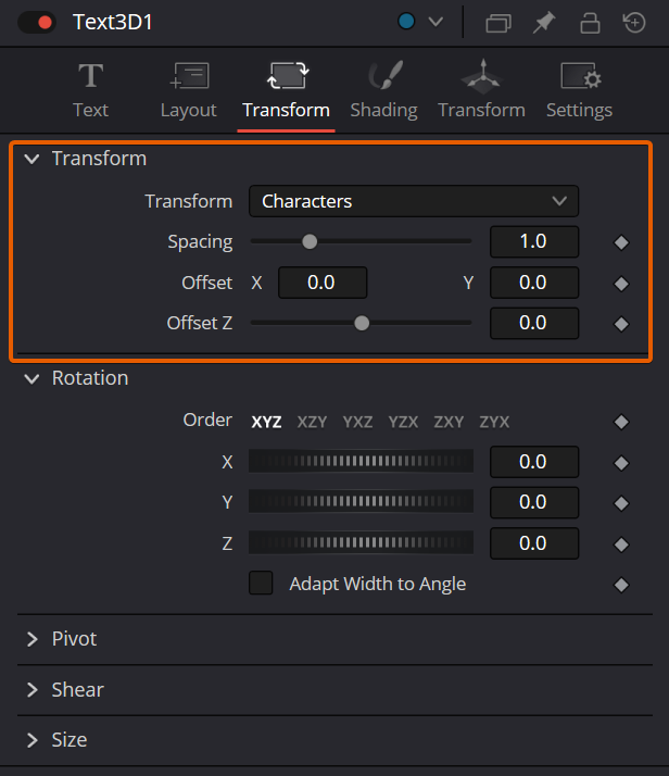
Transform
This menu determines the portion of the text affected by the transformations applied in this tab. Transformations can be applied to line, word, and character levels simultaneously. This menu is only used to keep the number of visible controls to a reasonable number.
Characters
Each character of text is transformed along its own center axis.
Words
Each word is transformed separately on the word’s center axis.
Lines
Each line of the text is transformed separately on that line’s center axis.
Spacing
The Spacing slider is used to adjust the amount of space between each line, word, or character. Values less than one usually cause the characters to begin overlapping.
Pivot X, Y, and Z
This provides control over the exact position of the axis. By default, the axis is positioned at the calculated center of the line, word, or character. The pivot control works as an offset, such that a value of 0.1, 0.1 in this control would cause the axis to be shifted downward and to the right for each of the text elements. Positive values in the Z-axis slider move the axis further along the axis (away from the viewer). Negative values bring the axis of rotation closer.
Rotation Order
These buttons are used to determine the order in which transforms are applied. X, Y, and Z would mean that the rotation is applied to X, then Y, and then Z.
X, Y, and Z
These controls can be used to adjust the angle of the text elements in any of the three dimensions.
Shear X and Y
Adjust these sliders to modify the slanting of the text elements along the X- and Y-axis.
Size X and Y
Adjust these sliders to modify the size of the text elements along the X- and Y-axis.
Shading
The Shading tab for the Text 3D node controls the overall appearance of the text and how lights affect its surface.
Opacity
Reducing the material’s opacity decreases the color and Alpha values of the specular and diffuse colors equally, making the material transparent and allowing hidden objects to be seen through the material.
Use One Material
Deselecting this option reveals a second set of Material controls for the beveled edge of the text.
Type
To use a solid color texture, select the Solid mode. Selecting the Image mode reveals a new external input on the node that can be connected to another 2D image.
Specular Color
Specular Color determines the color of light that reflects from a shiny surface. The more specular a material is, the glossier it appears. Surfaces like plastics and glass tend to have white specular highlights, whereas metallic surfaces like gold have specular highlights that tend to inherit their color from the material color. The basic shader material does not provide an input for textures to control the specularity of the object. Use nodes from the 3D Material category when more precise control is required over the specular appearance.
Specular Intensity
Specular Intensity controls the strength of the specular highlight. If the specular intensity texture port has a valid input, then this value is multiplied by the Alpha value of the input.
Specular Exponent
Specular Exponent controls the falloff of the specular highlight. The greater the value, the sharper the falloff, and the smoother and glossier the material appears. The basic shader material does not provide an input for textures to control the specular exponent of the object. Use nodes from the 3D Material category when more precise control is required over the specular exponent.
Image Source
This control determines the source of the texture applied to the material. If the option is set to Tool, then an input appears on the node that can be used to apply the output of a 2D node as the texture. Selecting Clip opens a file browser that can be used to select an image or image sequence from disk. The Brush option provides a list of clips found in the Fusionbrushes folder.
Bevel Material
This option appears only when the Use One Material checkbox control is selected. The controls under this option are an exact copy of the Material controls above but are applied only to the beveled edge of the text.
Position, Rotation, Shear, and Size
These transform controls act similarly to the transform controls in the Transform tab when a single shading element is enabled from the top of the Shading tab. However, when two or more shading elements are enabled, these transform controls are applied to the currently selected shading element. This allows you to independently control the position, rotation, shearing, and size of borders, fill colors, and shadows.
Text 3D Node Transform and Settings Tabs
The Transform and Settings tabs in the Inspector are duplicated in other 3D nodes. These common controls are described in detail
Text 3D Node Modifiers
Right-clicking within the Styled Text box displays a menu with the following text modifiers. Only one modifier can be applied to a Text 3D Styled Text box. Below is a brief list of the text specific modifiers
Animate
Use the Animate command to set to a keyframe on the entered text and animate the content over time.
Character Level Styling
The Text 3D node doesn’t support Character Level Styling directly. However, you can create a Text+ node first and modify its text field with a Character Level Styling modifier. Then either connect the Text 3D’s text field to the modifier that is now available or copy the Text+ node and paste its settings to the Text 3D node (right-click > Paste Settings)
Comp Name
Comp Name puts the name of the composition in the Styled Text box and is generally used as a quick way to create slates.
Follower
Follower is a text modifier that can be used to ripple animation applied to the text across each character in the text.
Publish
Publish the text for connection to other text nodes.
Text Scramble
A text modifier ID is used to randomize the characters in the text.
Text Timer
A text modifier is used to count down from a specified time or to output the current date and time.
Time Code
A text modifier is used to output Time Code for the current frame.
Connect To
Use this option to connect the text generated by this Text node to the published output of another node.

