Get 30+ hr of DaVinci Resolve courses & 400+ pre-made assets
As little as $15/month for all courses and pre-made assets
Particle Nodes
The Particle nodes are used to generate a large number of duplicated objects that automatically animate. They are used to create elements like falling rain, fireworks, smoke, pixie dust, and much more. There are endless possibilities. Particles in Fusion consist of a set of nodes that are strung together in a chain for generating, modifying, and rendering particles in a 2D or 3D scene.
To begin, every particle system you create must contain two fundamental nodes:
- pEmitter: Used to generate the particles and control their basic look, motion. and behavior.
- pRender: Used to render the output of the pEmitter into a 2D or 3D scene. When creating particles, you only ever view the pRender node.
The remaining particle nodes modify the pEmitter results to simulate natural phenomena like gravity, flocking, and bounce. The names of particle nodes all begin with a lowercase p to differentiate them from non-particle nodes. They can be found in the particles category in the Effects Library.
Particle Nodes Common Controls
Particle nodes share a number of identical controls in the inspector. This section describes the Style, Conditions, Region, and Settings tabs that are common among particle nodes.
Particle Nodes Style Tab
The Style Tab is common to the pEmitter, pSpawn, pChangeStyle, and pImage Emitter. It controls the appearance of the particles using general controls like type, size, and color.
Style
The Style menu provides access to the various types of particles supported by the Particle Suite. Each style has its specific controls, as well as controls it will share with other styles.
- Point: This option produces particles precisely one pixel in size. Controls that are specific to Point Style are Apply Mode and Sub Pixel Rendered.
- Apply Mode: This menu applies only to 2D particles. 3D particle systems are not affected. It includes Apply modes for Add and Merge. Add combines overlapping particles by adding together the color values of each particle. Merge uses a simple over operation to combine overlapping particles.
- Sub Pixel Rendered: This checkbox determines whether the point particles are rendered with Sub Pixel precision, which provides smoother-looking motion but blurrier particles that take slightly longer to render.
- Bitmap: This style produces particle cells based on an image file or another node in the Node editor. When this option is selected an orange image input appears on the node in the node editor. There are several controls for affecting the appearance and animation. In addition to the controls in the Style section, a Merge section is displayed at the bottom of the inspector when Bitmap is selected as the Style. The Merge section includes controls for additive or subtractive merges when the particle cells overlap.
- Animate Over Time: This menu includes three options for determining how movie files play when they are used as particle cell bitmaps. The Over Time setting plays the movie file sequentially. For instance, when the comps is on frame 2, frame 2 of the movie file is displayed, when the comp is on frame 3, frame 3 of the movie files is displayed and so on. If a particle cell is not generated until frame 50, it begins with frame 50 of the movie file. This causes all particle cells to use the same image on any give frame of the comp. The Particle Age setting causes each particle cell to begin with the first frame of the movie file, regardless of when the particle cell is generated. The Particle Birth Time setting causes each particle to begin with the frame that coincides with the frame of the particle cell birth time. For instance, if the particle is generated on frame 25, then it uses frame 25 of the movie file for the entire comp. Unlike the other two options, the Particle Birth Time setting holds the same frame for the duration of the comp
- Time Offset: This dial is used to slip or offset the starting frame used from the movie file. For instance, setting it to 10 will cause the movie file to start at frame 10 instead of frame 1.
- Time Scale: This slider is a multiplier on the frame. Instead of using an offset, it changes the starting frame by multiplying the frame by the value selected with the slider. For instance, if a value of 2 is selected then when the playhead reaches frame 2, the movie files displays frame 4 (2×2=4) and when the playhead reaches frame 8, the movie file displays frame 16 (8×2=16).
- Gain: The gain slider is a multiplier of the pixel value. It is used to apply a correction to the overall Gain of the Bitmap. Let’s say you have a bitmap particle cell that contains a pixel value of R0.5 G0.5 B0.4 and you add a Gain of 1.2, you end up with a pixel value of R0.6 G0.6, B0.48 (i.e., 0.4 * 1.2 = 0.48) while leaving black pixels unaffected. Higher values produce a brighter image, whereas lower values reduce both the brightness and the transparency of the image.
- Style Bitmap: This control appears when the Bitmap style is selected, along with an orange Style Bitmap input on the node’s icon in the Node view. Connect a 2D node to this input to provide images to be used for the particles. You can do this on the Node view, or you may drag and drop the image source node onto the Style Bitmap control from the Node Editor or Timeline, or right click on the control and select the desired source from the Connect To menu.
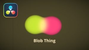
- Blob: This option produces large, soft spherical particles, with controls for Color, Size, Fade timing, Merge method, and Noise.
- Noise: This slider only applies to 2D Blob particles. The noise slider is used to introduce a computer generated Perlin noise pattern into the blob particles in order to give the blobs more texture. A setting of 0 introduces no noise to the Blob particles and a setting of 1 introduces the maximum amount of noise.
- Brush: This styles produces particle cells based on any image file located in the brushes directory. There are numerous controls for affecting the appearance and animation.
- Gain: The gain slider is a multiplier of the pixel value. It is used to apply a correction to the overall Gain of the image that is used as the Brush. Let’s say you have a brush particle cell that contains a pixel value of R0.5 G0.5 B0.4 and you add a Gain of 1.2, you end up with a pixel value of R0.6 G0.6, B0.48 (i.e., 0.4 * 1.2 = 0.48) while leaving black pixels unaffected. Higher values produce a brighter image, whereas lower values reduce both the brightness and the transparency of the image.
- Brush: This menu shows the names of any image files stored in the Brushes directory. The location of the Brushes directory is defined in the Preferences dialog, under Path Maps. The default is the Brushes subdirectory within Fusion’s install folder.
- Use Aspect From: The Use Aspect From menu includes three settings for the aspect ratio of the brush image. You can choose image format to use the brush image’s native aspect ration. Choose Frame Format to use the aspect ratio set in the Frame Format Setting in the Fusion Preferences, or choose Custom to enter your own Pixel X and Y dimensions.
- Line: This style produces straight line-type particles with optional “falloff.” The Size to Velocity control described below (under Size Controls) is often useful with this Line type. The Fade control adjusts the amount of falloff over the length of the line.
- Point Cluster: This style produces small clusters of single-pixel particles. Point Clusters are similar to the Point style; however, they are more efficient when a large quantity of particles is required. This style shares parameters with the Point style. Additional controls specific to Point Cluster style are Number of Points and Number Variance.
- Sub Pixel Rendered: This checkbox determines whether the point particles are rendered with Sub Pixel precision, which provides smoother-looking motion but blurrier particles that take slightly longer to render.
- Number of Points and Variance: The value of this control determines how many points are in each Point Cluster.
Particle Nodes Color Controls
The Color Controls select the color and Alpha values of the particles generated by the emitter.
Color Variance
These range controls provide a means of expanding the colors produced by the pEmitter. Setting the Red variance range at -0.2 to +0.2 will produce colors that vary 20% on either side of the red channel, for a total variance of 40%. If the pEmitter is set to produce R0.5, G0.5, B0.5 (pure gray), the variance shown above will produce points with a color range between R0.3, G0.5, B0.5, and R0.7, G0.5, B0.5. To visualize color space as values between 0-256 or as 0-65535, change the values used by Fusion using the Show Color As option provided in the General tab within the Preferences dialog.
Lock Color Variance
This checkbox locks the color variance of the particles. Unlocking this allows the color variance to be applied differently to each color channel, giving rise to a broader range of colors.
Color Over Life
This standard gradient control allows for the selection of a range of color values to which the particle will adhere over its lifetime. The left point of the gradient represents the particle color at birth. The right point shows the color of the particle at the end of its lifespan.
Additional points can be added to the gradient control to cause the particle color to shift throughout its life.
This type of control can be useful for fire-type effects (for example, the flame may start blue, turn orange, and end a darker red). The gradient itself can be animated over time by right-clicking on the control and selecting Animate from the contextual menu. All points on the gradient will be controlled by a single Color Over Life spline, which controls the speed at which the gradient itself changes. You may also use the From Image modifier, which produces a gradient from the range of colors in an image along a line between two points.
Particle Nodes Size Controls
The majority of the Size Controls are self-explanatory. The Size and Size Variance controls are used to determine the size and degree of size variation for each particle. It is worth noting that the Point style does not have size controls (each point is a single pixel in size, and there is no additional control).
When a Bitmap Particle style is used, a value of 1.0 indicates that each particle should be the same size as the input bitmap. A value of 2.0 will scale the particle up in size by 200%. For the best quality particles, always try to make the input bitmap as big, or bigger, than the largest particle produced by the system.
For the Point Cluster style, the size control adjusts the density of the cluster, or how close together each particle will get.
There are additional size controls that can be used to adjust further the size of particles based on velocity and depth.
Size to Velocity
This increases the size of each particle relative to the velocity or speed of the particle. The velocity of the particle is added to the size, scaled by the value of this control.
1.0 on this control, such as for a particle traveling at 0.1, will add another 0.1 to the size (velocity * size to velocity + size = new size). This is most useful for Line styles, but the control can be used to adjust the size of any style.
Size Z Scale
This control measures the degree to which the size of each particle changes according to its Z position. The effect is to exaggerate or reduce the impact of perspective. The default value is 1.0, which provides a relatively realistic perspective effect.
Objects on the focal plane (Z = 0.0) will be actual-sized. Objects farther along Z will become smaller. Objects closer along Z will get larger.
A value of 2.0 will exaggerate the effect dramatically, whereas a value of 0.0 will cancel the effects of perspective entirely.
Size Over Life
This spline control determines the size of a particle throughout its lifespan. The vertical scale represents a percentage of the value defined by the Size control, from 0 to 200%. The horizontal scale represents a percentage of the particle’s lifespan (0 to 100%).
This graph supports all the features available to a standard spline editor. These features can be accessed by right-clicking on the graph. It is also possible to view and edit the graph spline in the larger Spline Editor
Particle Nodes Fade Controls
This simple range slider provides a mechanism for fading a particle at the start and end of its lifetime. Increasing the Fade In value will cause the particle to fade in at the start of its life. Decreasing the Fade Out value will cause the particle to fade out at the end of its life.
This control’s values represent a percentage of the particle’s overall life, therefore, setting the Fade In to 0.1 would cause the particle to fade in over the first 10% of its total lifespan. For example, a particle with a life of 100 frames would fade in from frame 0…10.
Particle Nodes Merge Controls
This set of particle controls affects the way individual particles are merged together. The Subtractive/ Additive slider works as documented in the standard Merge node. The Burn-In control will cause the particles to overexpose, or “blow out,” when they are combined.
None of the Merge controls will have any effect on a 3D particle system.
Particle Nodes Blur Controls
This set of particle controls can be used to apply a Blur to the individual particles. Blurring can be applied globally, by age, or by Z depth position.
None of the Blur controls will have any effect on a 3D particle system.
Blur (2D) and Blur Variance (2D)
These controls apply blur to each particle. Unlike the Blur in the pRender node, this is applied to each particle independently before the particles are merged together. The Blur Variance slider modifies the amount of blur applied to each particle.
Blur Over Life
This spline graph controls the amount of blur that is applied to the particle over its life. The vertical scale represents a percentage of the value defined by the Blur control. The horizontal scale represents a percentage of the particle’s lifespan.
This graph supports all of the features available to a standard Spline Editor. These features can be accessed by right-clicking on the graph. It is also possible to view and edit the spline in the larger Spline editor.
Z Blur (DoF) (2D) and DoF Focus
This slider control applies blur to each particle based on its position along the Z axis.
The DoF Focus range control is used to determine what area of the image remains in focus. Lower values along Z are closer to the camera. Higher values are farther away. Particles within the range will remain in focus. Particles outside that range will have the blur defined by the Z Blur control applied to them.
Particle Nodes Conditions Tab
The Conditions tab limits the particles that are affected by the node’s behavior. You can limit the particle using probability or more specifically using sets.
Probability
The Probability slider determines the percentage of chance that the node affects any given particle.
The default value of 1.0 affects all particles. A setting of 0.6 would mean that each particle has a 60 percent chance of being affected by the control.
Probability is calculated for each particle on each frame. For example, a particle that is not affected by a force on one frame has the same chance of being affected on the next frame.
Start/End Age
This range control can be used to restrict the effect of the node to a specified percentage of the particle lifespan.
For example, to restrict the effect of a node to the last 20 percent of a particle’s life, set the Start value to 0.8, and the End value remains at 1.0. The node on frames 80 through 100 only affects a particle with a lifespan of 100 frames.
Set Mode Menu
The Set Mode menu drives how the particle node influences the active particle sets. There are three options from this menu:
- Ignore Sets: The particle node disregards the state of the Set checkboxes and applies to all nodes.
- Affect Specified Sets: The particle node applies its behavior to the active Set checkboxes only.
- Ignore Specified Sets: The particle node applies its behavior to the inactive Set checkboxes only.
Set #
The state of a Set # checkbox determines if the Particle node’s effect will be applied to the particles in the set. It allows you to limit the effects of some nodes to a subset of particles.
Sets are assigned by the nodes that create particles. These include the pEmitter, pImage Emitter, pChangeStyle, and the pSpawn nodes.
Particle Nodes Region Tab
The Region tab is used to restrict the node’s effect to a geometric region or plane, and to determine the area where particles are created if it’s a pEmitter node or where the behavior of a node has influence.
The Region tab is common to almost all particle nodes. In the pEmitter node Emitter Regions are used to determine the area where particles are created. In most other tools it is used to restrict the tool’s effect to a geometric region or plane. There are seven types of regions, each with its own controls. Only one emitter region can be set for a single pEmitter node. If the pRender is set to 2D, then the emitter region will produce particles along a flat plane in Z Space. 3D emitter regions possess depth and can produce particles inside a user-defined, three-dimensional region.
Region Mode Menu
The Region Mode menu includes seven types of regions to define the area, each with its controls.
- All: In 2D, the particles will be created anywhere within the boundaries of the image. In 3D, this region describes a cube 1.0 x 1.0 x 1.0 units in size.
- Bézier: Bézier mode uses a user-created polyline to determine the region where particles are created. The Bézier mode works in both 2D and 3D modes; however, the Bézier polyline region can only be created in 2D. To animate the shape of the polyline over time or to connect it to another polyline, right-click the Shape animation label at the bottom of the inspector and select the appropriate option from the drop-down menu.
- Bitmap: A Bitmap source from one of the other nodes in the composition will be used as the region where particles are born.
- Cube: A full 3D Cube is used to determine the region within which particles are created. The height, width, depth, and XYZ positions can all be determined by the user and be animated over time.
- Line: A simple line control determines where particles are created. The line is composed of two end-points, which can be connected to Paths or Trackers, as necessary. This type of emitter region includes X, Y, and Z position controls for the start and end of the line
- Mesh: Any 3D Mesh can be used as a region. In Mesh mode, the region can also be restricted by the Object ID using the ObjectID slider. See below for a more in-depth explanation of how mesh regions work.
- Rectangle: The Rectangle region type is like the Cube type, except that this region has no depth in Z space. Unlike other 2D emitter regions, this region can be positioned and rotated in Z space.
- Sphere: This is a spherical 3D emitter region with Size and Center Z controls. Sphere (3D) is the default region type for a new pEmitter node.
Particle Nodes Mesh Regions
Region Type
The Region Type drop-down menu allows you to choose whether the region will include the inner volume or just the surface. For example, with a pEmitter mesh region, this determines if the particles emit from the surface or the full volume.
Winding Rule and Winding Ray Direction
The Winding Rule and Winding Ray Direction parameters determine how the mesh region handles particle creation with meshes that are not closed, as is common in many meshes imported from external applications. This scenario is common with imported mesh geometry, and even geometry that appears closed will frequently appear to “leak” thanks to improperly welded vertices.
To determine if a particle is in the interior of an object, a ray is cast from infinity through that particle and then out to -infinity. The Winding Ray Direction determines which direction this ray is cast in. Each time a surface is pierced by the ray, it is recorded and added onto a total to generate a winding number. Going against a surfaces normal counts as +1, and going with the normal counts as -1.
The Winding Rule is then used to determine what is inside/outside. For example, setting the Winding Rule to Odd means that only particles with odd values for the winding number are kept when creating the particles. The exact same approach is used to ensure that polylines that intersect themselves are closed properly.
Limit By ObjectID
Selecting this checkbox allows the Object ID slider to select the ObjectID used as part of the region.
Particle Nodes Style Tab
The Style tab exists in the pEmitter, pSpawn, pChangeStyle, and pImage Emitter. It controls the appearance of the particles, allowing the look of the particles to be designed and animated over time.
Style
The Style menu provides access to the various types of particles supported by the Particle Suite. Each style has its specific controls, as well as controls it will share with other styles.
- Point Style: This option produces particles precisely one pixel in size. Controls that are specific to Point style are Apply Mode and Sub Pixel Rendered.
- Bitmap Style and Brush Style: Both the Bitmap and Brush styles produce particles based on an image file. The Bitmap style relies on the image from another node in the node tree, and the Brush style uses image files in the Brushes directory. They both have numerous controls for affecting their appearance and animation, described below.
- Blob Style: This option produces large, soft spherical particles, with controls for Color, Size, Fade timing, Merge method, and Noise.
- Line Style: This style produces straight line-type particles with optional “falloff.” The Size to Velocity control described below (under Size Controls) is often useful with this Line type. The Fade control adjusts the amount of falloff over the length of the line.
- Point Cluster Style: This style produces small clusters of single-pixel particles. Point Clusters are similar to the Point style; however, they are more efficient when a large quantity of particles is required. This style shares parameters with the Point style. Additional controls specific to Point Cluster style are Number of Points and Number Variance.
Style Options
The following options appear only on some of the styles, as indicated below.
Apply Mode (Point and Point Cluster)
This control applies only to 2D particles; 3D particle systems are not affected.
- Add: Overlapping particles are combined by adding together the color values of each particle.
- Merge: Overlapping particles are merged.
Sub Pixel Rendered (Point and Point Cluster)
This checkbox determines whether the point particles are rendered with Sub Pixel precision, which provides smoother-looking motion but blurrier particles that take slightly longer to render.
Number of Points and Variance (Point Cluster)
The value of this control determines how many points are in each Point Cluster.
Animate (Bitmap Style)
If the Bitmap source is a movie file or image sequence, this menu determines which frame is grabbed from the source and applied to newly-created particles.
- Over Time: All particles use the image produced by the Style Bitmap node at the current time, and change to each successive image together in step, as time increases. A particle created at frame 1 will contain the image at frame 1 of the Style Bitmap. At frame 2, the original particle will use the image from frame 2, and so will any new particles. All created particles will share the same bitmap image from their source at all times.
- Particle Age: Each particle animates through the sequence of images provided by the Style Bitmap node, independently of other particles. In other words, an individual particle’s appearance is taken from the Style Bitmap node at successive times, indexed by its age.
- Particle Birth Time: New particles take the image from the Style Bitmap node at the current time and keep it unchanged until the end of the particle’s lifespan. Thus, particles generated on a given frame will all have the same appearance and will stay that way.
Time Offset (Bitmap Style)
This control allows the Bitmap source frame to be offset in time from the current frame.
Time Scale (Bitmap Style)
This control scales the time range of the source bitmap images by a specified amount. For example, a scale of 2 will cause the particle created at frame 1 to be read from the bitmap source at frame 2.
Gain (Bitmap and Brush Style)
This control applies a gain correction to the image used as the bitmap. Higher values produce a brighter image, whereas lower values reduce both the brightness and the transparency of the image.
Style Bitmap (Bitmap Style)
This control appears when the Bitmap style is selected, along with an orange Style Bitmap input on the node’s icon in the Node view. Connect a 2D node to this input to provide images to be used for the particles. You can do this on the Node view, or you may drag and drop the image source node onto the Style Bitmap control from the Node Editor or Timeline, or right-click on the control and select the desired source from the Connect To menu.
Brush (Brush Style)
This menu shows the names of any image files stored in the Brushes directory. The location of the Brushes directory is defined in the Preferences dialog, under Path Maps. The default is the Brushes subdirectory within Fusion’s install folder. If no images are in this directory, the only option in the menu will be None, and no particles will be rendered.
Noise (Blob Style)
Increasing this control’s value will introduce grain-type noise to the blobby particle.
Fade (Line Style)
The Fade control adjusts the falloff over the line particle’s length.
The default value of 1.0 causes the line to fade out completely by the end of the length.
Particle Nodes Color Controls
The Color Controls select the color and Alpha values of the particles generated by the emitter.
Color Variance
These range controls provide a means of expanding the colors produced by the pEmitter. Setting the Red variance range at -0.2 to +0.2 will produce colors that vary 20% on either side of the red channel, for a total variance of 40%. If the pEmitter is set to produce R0.5, G0.5, B0.5 (pure gray), the variance shown above will produce points with a color range between R0.3, G0.5, B0.5, and R0.7, G0.5, B0.5.
To visualize color space as values between 0-256 or as 0-65535, change the values used by Fusion using the Show Color As option provided in the General tab within the Preferences dialog.
Lock Color Variance
This checkbox locks the color variance of the particles. Unlocking this allows the color variance to be applied differently to each color channel, giving rise to a broader range of colors.
Color Over Life
This standard gradient control allows for the selection of a range of color values to which the particle will adhere over its lifetime.
The left point of the gradient represents the particle color at birth. The right point shows the color of the particle at the end of its lifespan.
Additional points can be added to the gradient control to cause the particle color to shift throughout its life.
This type of control can be useful for fire-type effects (for example, the flame may start blue, turn orange and end a darker red). The gradient itself can be animated over time by right-clicking on the control and selecting Animate from the contextual menu. All points on the gradient will be controlled by a single Color Over Life spline, which controls the speed at which the gradient itself changes. You may also use the From Image modifier, which produces a gradient from the range of colors in an image along a line between two points.

About the Author
Justin Robinson is a Certified DaVinci Resolve, Fusion & Fairlight instructor who is known for simplifying concepts and techniques for anyone looking to learn any aspect of the video post-production workflow. Justin is the founder of JayAreTV, a training and premade asset website offering affordable and accessible video post-production education. You can follow Justin on Twitter at @JayAreTV YouTube at JayAreTV or Facebook at MrJayAreTV
Get 30+ hr of DaVinci Resolve courses & 400+ pre-made assets
As little as $15/month for all courses and pre-made assets